
A few months ago a design problem emerged on the ZZ9000 boards for Amiga, which was immediately reported and extensively documented by MNT Research GmbH of Lukas F. Hartmann and supported by an information campaign dedicated to all buyers, including me. In practice, in the ZZ9000 boards of the R-1 and R-2 revisions, the tracks for the 1.8 Volt and 3.3 Volt voltage lines supplying the ZYNQ module are merged. According to the original page of the report, the problem occurred because pin 93 of connector U12 was documented as XADC supply in the MYIR documentation but it was not specified that this was already internally connected to 1.8 Volts, that's how the error occurred.
This incorrect connection causes an alteration of the I/O supply voltages connected to the ZYNQ module, so while in normal operation these are indicated as suitable up to a maximum of 1.9 volts, at present they are 3.3 volts. As a result, the ZYNQ module, being overcharged, heats up almost 10 degrees Celsius more than it should, potentially causing long-term damage.
|
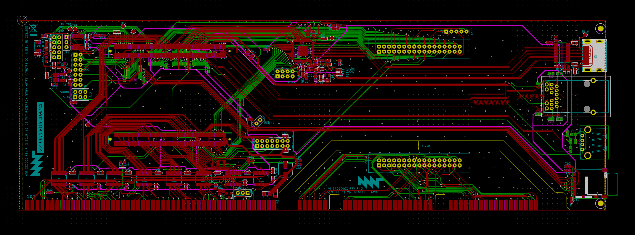
Pic.1: Layout elettronico della ZZ9000 |
|
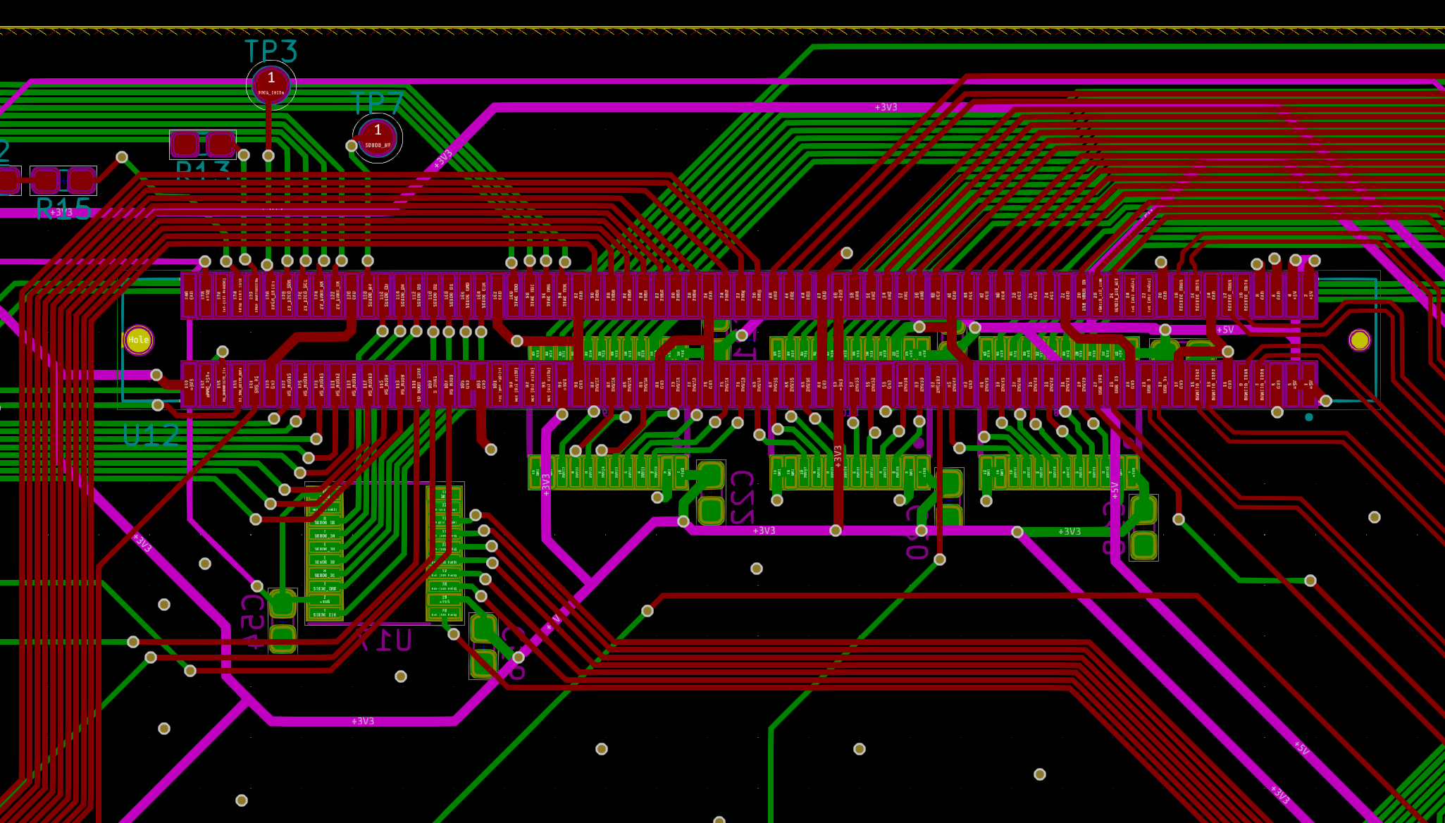
Pic.2: Dettaglio Layout della zona |
|
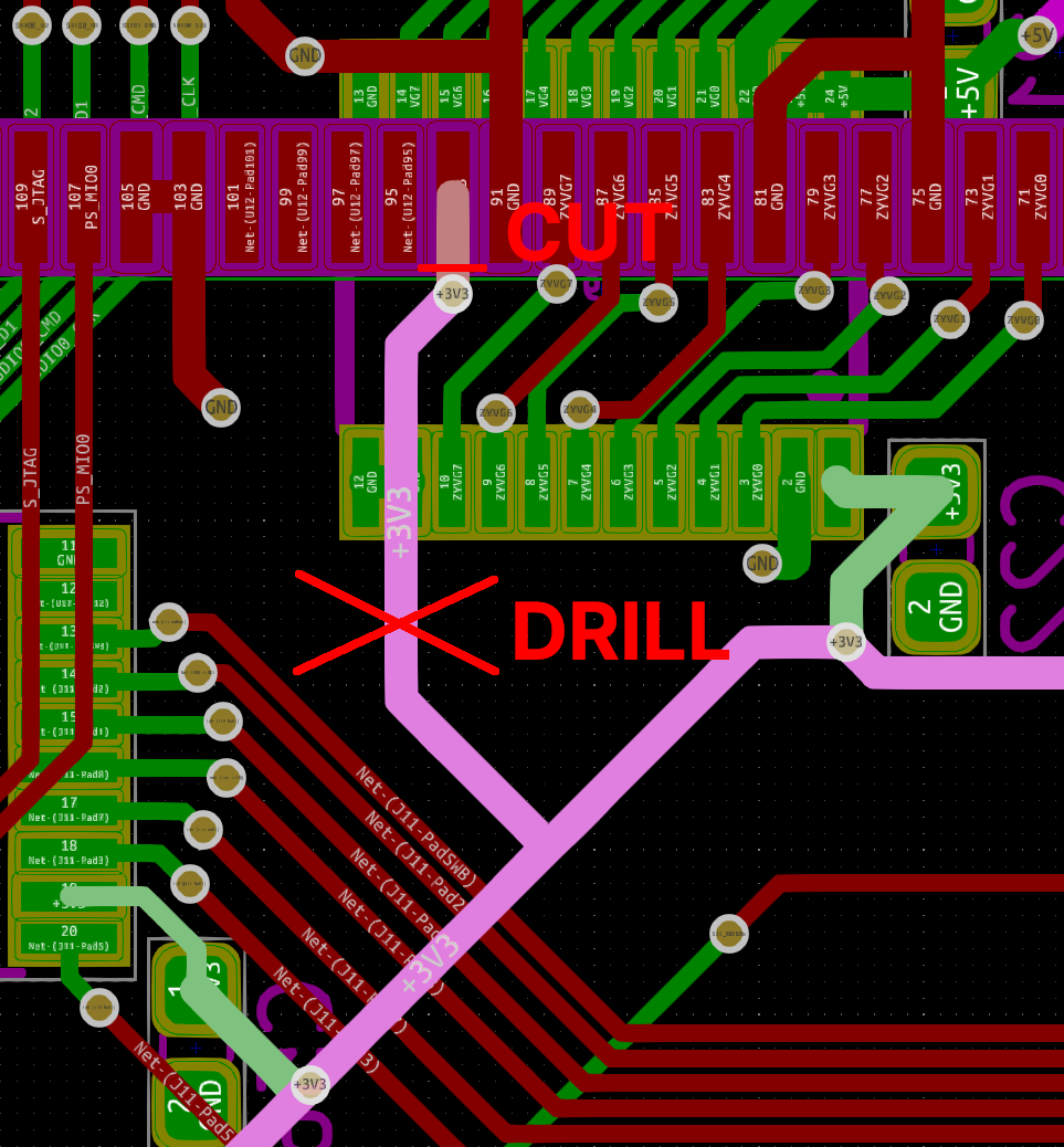
Pic. 3: dettaglio delle possibili interruzioni |
|
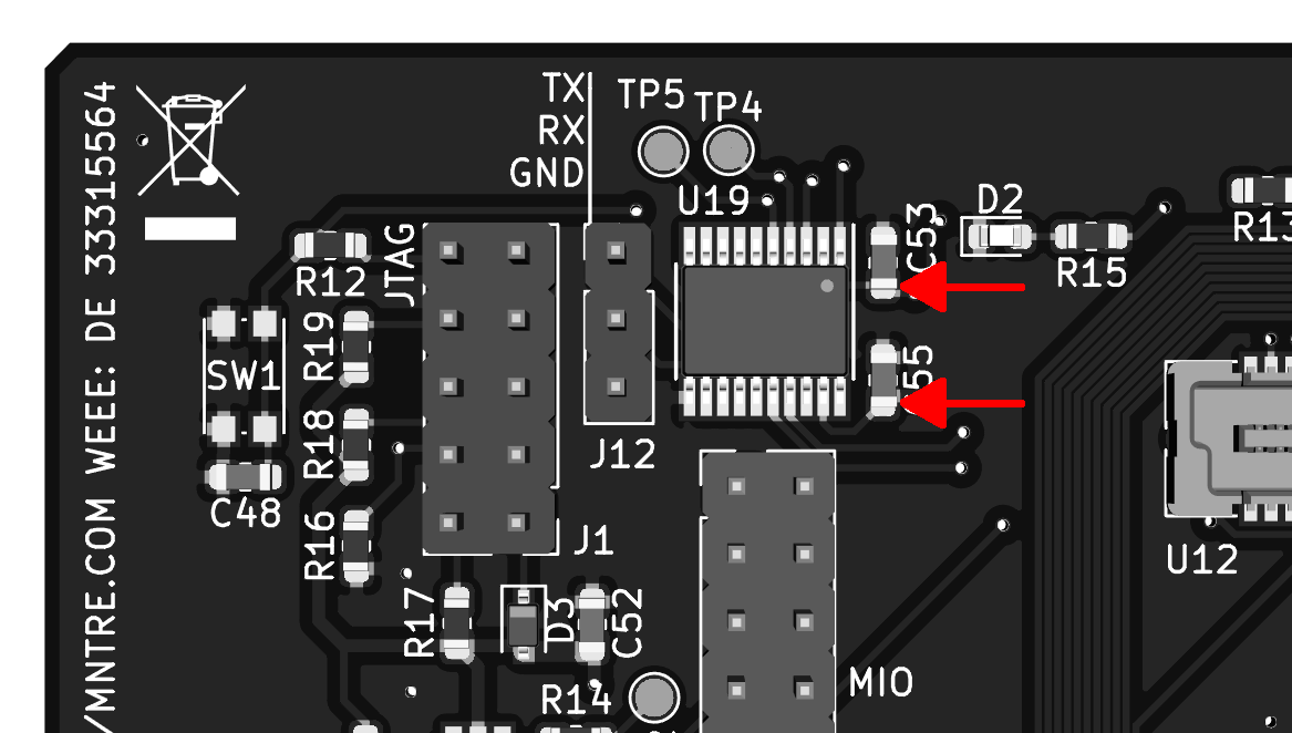
Pic. 4: Punti di misurazione per controllare l'effettiva interruzione della pista |
How to correct the problem:
Two methods have been suggested to solve this power supply problem: the first is to cut the lead that connects pin 93 of the U12 connector right at that pin, and the second is to drill a 1millimetre diameter hole in the board at the exact point where the lead that carries the voltage always passes through to pin 93 of U12. The hole should then be cleaned of any residue in order to prevent metal parts extracted then wander free to potentially short out who knows what, once reassembled, but not only, being the board a sandwich of 4 layers, you must be very careful so that inside the hole itself there are no metal residues that can short-circuit the voltage line with the ground of the board causing a cataclysmic crash to the system itself.
For all these reasons I preferred to make this modification on my ZZ9000 using the first method, that is cutting the track with a cutter.
To make this modification, it is not enough to have a cutter, but it is necessary to be able to see very well with a good magnification the interested area where we are going to operate with the tip of the cutter, since the dimensions are really very small and you can easily risk to make damages. To get a good view I used a Galaxy S4 on a small articulated pedestal, a miracast key and a 24-inch FullHD monitor. Once connected the miracast key to the monitor I fixed the mobile phone in correspondence of the card with the small pedestal, operating the camera I sent the video to the miracast key, in this way it was possible to enlarge well the part where I was going to operate with the cutter and document the operation with the recorded video.
The first thing to do after removing the board from the computer is to remove the ZYNQ module that covers its plug-in connectors. Once you've removed the module, simply locate the modified pin on the U12 connector. I've taken a few photos of this for clarity. For those who want to then I published a video with all the stages of the intervention. Once you have identified the small track to be cut, you can proceed with a cutter. The operation is rather delicate, you have to use a lot of force otherwise you risk going to hit or cut something else. Fortunately, the track is very well positioned and there are no other tracks in the vicinity that could be at risk.
Once the cut has been made, you can check it with a tester set to detect continuity and then measure at the contact points shown in Pic. 4. At this point, all that remains is to verify the correct voltage with the dedicated utility, the ZZ Top (...yes it is also beautiful music...) . For all the steps I refer you to the video below hoping it is clear enough.


Leave a Comment